Gas Buildup in Manifold CVD Machines: Causes, Effects, and Prevention
Gas buildup inside a CVD manifold can restrict chemical flow, disturb chamber pressure, create particles, and reduce the quality of deposited films.

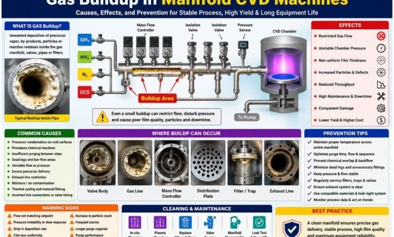
Introduction
Gas buildup in manifold CVD machines happens when precursor vapours, chemical by-products, powders, or solid films collect inside the gas-delivery system.
The problem may develop inside pipes, valves, filters, mass flow controllers, pressure sensors, gas-distribution plates, vacuum lines, or exhaust components. It usually begins when chemicals condense on a cold surface, react before reaching the chamber, or remain trapped because the system is not purged correctly.
As the deposit grows, the machine may experience unstable gas flow, pressure alarms, uneven coatings, increased particle contamination, and longer maintenance downtime.
Chemical vapour deposition is widely used to place thin layers of materials such as silicon, silicon dioxide, and silicon nitride onto semiconductor wafers.
What Is a Manifold in a CVD Machine?
A CVD manifold is the network of valves, pipes, flow controllers, and sensors that delivers gases or chemical vapours to the process chamber.
Its main duties include:
- Carrying precursor chemicals safely
- Controlling the amount of each gas
- Separating chemicals until the correct process step
- Purging unused chemicals from the system
- Maintaining stable pressure and temperature
- Delivering an even gas mixture to the chamber
The manifold must remain clean because even a small restriction can change how much precursor reaches the wafer.
What Does Gas Buildup Really Mean?
The term “gas buildup” does not usually mean that a pocket of gas has become permanently trapped.
In most cases, a gas or vapour changes into a liquid, powder, or solid material and sticks to an internal surface. The buildup may contain:
- Condensed precursor liquid
- Unreacted chemical residue
- Oxide or nitride deposits
- Chloride salts
- Carbon-rich material
- Metal-containing particles
- Powder created by an early chemical reaction
- Flakes released from old internal coatings
These materials can slowly narrow the gas path or break loose and enter the process chamber.
Main Causes of Gas Buildup in Manifold CVD Machines
1. Precursor Condensation
Many liquid and solid CVD precursors are heated so that they can travel through the machine as vapour.
If part of the delivery line becomes too cold, the vapour can return to liquid or solid form. The material then sticks to the wall of the pipe, valve, or sensor.
Common cold spots may develop around:
- Unheated fittings
- Valve bodies
- Mass flow controllers
- Pressure sensors
- Tube bends
- Damaged heater jackets
- Poorly insulated connections
- Long sections of gas tubing
A single temperature sensor may show a normal value while another small part of the manifold remains cold. Therefore, the complete gas path must be checked rather than only the main heated line.
2. Premature Chemical Reactions
CVD chemicals are supposed to react inside the process chamber. However, they may react inside the manifold if two incompatible gases meet too early.
This can happen because of:
- A leaking isolation valve
- Incorrect valve timing
- Gas backflow from the chamber
- Poor pressure control
- Incorrect gas-line connections
- Weak purging between process steps
- A damaged valve seat
- Reactive gases sharing the same line
An early reaction may create powder or a hard film inside the gas manifold.
The material can continue growing during every production cycle until it reduces gas flow or damages a component.
3. Insufficient Purging
An inert gas such as nitrogen or argon is often used to clear unused chemicals from gas lines.
If the purge is too short or too weak, some precursor may remain inside the system. It can later react with the next chemical entering the line.
Poor purging may result from:
- Low purge-gas pressure
- Low flow rate
- Short purge time
- Blocked purge passages
- Poor valve sequencing
- Large internal pipe volume
- Long gas lines
- Restricted exhaust flow
Simply increasing the purge time may not solve the problem when the real cause is a leaking valve, cold spot, or blocked exhaust line.
4. Dead Legs and Low-Flow Areas
A dead leg is a section of pipe or a fitting where very little gas moves.
Unused branches, oversized fittings, long sensor connections, and complex valve arrangements can create these low-flow areas.
Chemical vapour may remain trapped in a dead leg after the main gas flow stops. The trapped material then has more time to:
- Condense
- Decompose
- React with moisture
- Meet another precursor
- Form a solid deposit
Short and direct gas paths are generally easier to heat, purge, and maintain.
5. Unstable Flow or Pressure
CVD processes depend on accurate gas flow and stable chamber pressure.
A problem with a mass flow controller, regulator, pressure controller, throttle valve, or vacuum pump can change the movement of chemicals through the system.
Low flow may allow a precursor to remain inside the manifold for too long. High pressure may push process gases backwards into another gas line.
Pressure instability can also allow chamber by-products to move towards upstream manifold components.
6. Excess Precursor Delivery
Supplying more precursor than the process can use may increase the amount of unreacted chemical leaving the chamber.
This excess material may condense or react in the chamber outlet, vacuum foreline, pump, or exhaust system.
It can also encourage unwanted gas-phase reactions that create powder before the chemicals reach the wafer surface.
7. Exhaust Restrictions
The exhaust system helps remove unused precursor and reaction by-products.
If a filter, trap, pipe, scrubber, or vacuum line becomes restricted, chamber pressure and gas residence time may increase.
Reactive chemicals then remain in the system longer, giving them more time to form deposits.
A blocked exhaust path may also produce:
- Slow chamber pump-down
- Pressure alarms
- Unstable deposition rates
- Backflow
- Increased pump load
- Poor purge performance
8. Moisture or Air Entering the System
Some CVD precursors react strongly with oxygen or moisture.
A small leak, poor maintenance procedure, or incomplete system drying can allow air or water vapour to enter the manifold.
The reaction may form:
- Oxides
- Hydroxides
- Corrosive material
- Sticky residue
- Fine particles
Moisture contamination can also damage valves, seals, and flow-control components.
9. Thermal Cycling
Internal deposits expand when the machine becomes hot and contract when it cools.
The deposit and metal surface may expand at different rates. Repeated heating and cooling can therefore cause the coating to crack.
Small pieces may then break away and travel through the gas stream.
This can create serious particle contamination even when the deposit is not large enough to block the pipe.
Common Warning Signs
Gas buildup normally develops slowly. The machine may continue operating while process quality gradually becomes worse.
Important warning signs include:
| Warning sign | Possible meaning |
|---|---|
| Gas flow does not match the setpoint | Restriction in a valve, tube, or controller |
| Chamber pressure responds slowly | Reduced gas or exhaust conductance |
| Deposition rate begins falling | Less precursor reaching the chamber |
| Film thickness becomes uneven | Poor gas distribution |
| Particle count increases | Deposit cracking or powder formation |
| More frequent pressure alarms | Blockage, valve problem, or pump issue |
| Longer purge time is required | Residue remaining in the gas path |
| Process results vary between runs | Changing internal flow conditions |
| Pump performance decreases | Material entering the vacuum system |
| A valve opens or closes slowly | Internal contamination or damage |
| Powder appears during maintenance | Chemical reaction by-products |
| Heater power changes unexpectedly | Insulation or temperature-control problem |
These signs do not always prove that buildup is present. Similar symptoms may come from worn components, calibration errors, gas-supply problems, or vacuum leaks.
How Gas Buildup Affects the CVD Process
Reduced Gas Delivery
A deposit reduces the open area inside a pipe or valve.
The machine may command the correct gas flow, but the actual amount reaching the process chamber may become lower or less stable.
Uneven Film Thickness
A partly blocked manifold or showerhead can distribute gas unevenly across the wafer.
One area may receive more precursor than another, causing differences in:
- Film thickness
- Chemical composition
- Electrical properties
- Surface texture
- Stress
- Adhesion
Process Drift
Buildup usually grows over time.
The process may slowly move away from its original qualified condition. Operators may notice small changes in pressure, deposition rate, uniformity, or gas consumption before a major failure occurs.
Particle Contamination
Powder and broken pieces of internal deposits can enter the chamber and land on the wafer.
Even a very small particle may damage a semiconductor structure or reduce production yield.
Valve and Sensor Damage
Deposits can affect moving and measuring components.
Possible damage includes:
- Valve seats failing to seal
- Diaphragms becoming stiff
- Pressure sensors giving unstable readings
- Mass flow controllers losing accuracy
- Filters becoming blocked
- Seals becoming chemically damaged
Vacuum Pump Problems
Unreacted chemicals and powders may travel into the vacuum pump.
This can contaminate pump oil, damage internal parts, increase power use, or shorten the pump’s working life.
Increased Downtime
A small deposit may be handled during planned maintenance.
A severe restriction may require the manifold to be opened, cleaned, leak-tested, and qualified again. Some damaged components may need complete replacement.
How to Diagnose Gas Buildup
CVD gas systems may use toxic, corrosive, flammable, or highly reactive chemicals. OSHA identifies gases including silane, ammonia, phosphine, arsine, hydrogen, and other hazardous materials in semiconductor deposition operations.
Only trained and authorised personnel should inspect or service the equipment.
Review Process History
Compare current machine data with a period when the process was operating correctly.
Check:
- Commanded and actual gas flow
- Chamber pressure
- Manifold pressure
- Pump-down time
- Valve response
- Purge duration
- Heater temperatures
- Precursor usage
- Deposition rate
- Film uniformity
- Particle results
- Vacuum-pump performance
A slow change over many cycles may point towards growing contamination.
Check the Full Temperature Path
Inspect every heated part between the precursor source and the chamber.
This may include:
- Precursor container
- Vaporiser
- Delivery pipe
- Filters
- Valves
- Mass flow controller
- Pressure sensor
- Manifold block
- Chamber inlet
Look for a sudden temperature drop or an area with damaged insulation.
Test Valve Operation
A valve may appear to operate correctly in the control software but still leak internally.
Valve testing should confirm that each component opens, closes, and seals according to the equipment manufacturer’s requirements.
Examine Pressure Response
A restricted pipe changes how quickly pressure rises or falls.
Technicians may compare pressure-response data with a known clean condition using an approved inert-gas test.
Inspect Filters and Traps
A full trap or blocked filter can affect the entire gas-delivery and exhaust system.
Filters and traps should be checked according to the approved maintenance schedule.
Identify the Deposit
The deposit’s location, colour, hardness, and texture may provide clues, but appearance alone is not always enough.
Laboratory analysis may be needed to identify whether it contains:
- Unreacted precursor
- Oxide
- Nitride
- Carbon
- Metal
- Chloride
- Corrosion products
Knowing the chemical composition is important because the wrong cleaning method could create a dangerous reaction.
Safe Cleaning Methods
There is no single cleaning method for every CVD machine.
The correct procedure depends on:
- Precursor chemistry
- Deposit composition
- Manifold material
- Valve design
- Machine model
- Process temperature
- Safety requirements
Possible approved methods include:
- In-situ chamber cleaning
- Remote-plasma cleaning
- Controlled inert-gas purging
- Replacement of contaminated valves
- Filter or trap replacement
- Removal and professional cleaning of manifold parts
- Approved chemical cleaning
- Replacement of heavily coated tubing
Fluorinated gases are commonly used in semiconductor manufacturing for CVD chamber cleaning, although manufacturers also work to improve gas use and reduce emissions.
Cleaning recipes should always come from the equipment manufacturer or an approved process engineer.
Operators should never experiment with cleaning chemicals inside a contaminated gas manifold.
How to Prevent Gas Buildup
Maintain Stable Temperatures
Keep the precursor above its required condensation temperature throughout the delivery path.
Pay special attention to:
- Valves
- Fittings
- Sensors
- Filters
- Tube bends
- Connections between heater zones
Temperature settings must remain within the chemical supplier’s and machine manufacturer’s approved limits. Excess heat can also cause a precursor to decompose.
Improve Purging
The purge must remove enough residual material before the next reactive gas enters.
Purge performance should be reviewed whenever there is a change in:
- Precursor type
- Gas flow
- Pressure
- Pipe length
- Valve design
- Process recipe
- Chamber configuration
Prevent Chemical Overlap
Reactive chemicals should remain separated until they enter the intended reaction area.
Reliable isolation valves, correct timing, and stable pressure help prevent early reactions.
Reduce Dead Volume
Where the equipment design allows it, remove unused branches and shorten unnecessarily long gas paths.
A simple manifold is normally easier to purge and keep at a stable temperature.
Maintain Filters and Traps
Filters and traps should be replaced before they become fully blocked.
Waiting for complete failure may allow pressure changes, contamination, or backflow to affect other equipment.
Monitor the Exhaust System
Check vacuum lines, pumps, traps, and scrubbers as part of the same maintenance programme as the gas manifold.
The exhaust system must safely handle unused process gases and chemical by-products.
Use Compatible Materials
Pipes, seals, valves, and sensors must be suitable for the process chemistry and temperature.
Corrosion can roughen internal surfaces and give deposits more places to attach.
Track Machine Condition
Maintenance should not depend only on calendar time.
Useful indicators include:
- Number of production cycles
- Total deposition time
- Precursor consumption
- Flow drift
- Pressure-response changes
- Particle trends
- Pump load
- Trap condition
- Film-uniformity changes
Condition-based maintenance can help technicians respond before a small deposit becomes a serious blockage.
Prevention Checklist
Before Production
- Confirm the correct precursor and carrier gas.
- Check every required heater zone.
- Verify purge-gas flow and pressure.
- Confirm valve and flow-controller communication.
- Check chamber pressure.
- Inspect trap and filter status.
- Review recent process alarms.
During Production
- Monitor actual and commanded gas flow.
- Watch for pressure drift.
- Track deposition rate.
- Review film-uniformity results.
- Record particle levels.
- Investigate repeated alarms instead of only resetting them.
During Maintenance
- Follow the approved shutdown procedure.
- Isolate and purge hazardous gas lines.
- Treat unidentified residue as dangerous.
- Inspect common cold spots.
- Check valve sealing.
- Replace damaged insulation.
- Service filters and traps.
- Perform leak testing.
- Requalify the process before returning to production.
Frequently Asked Questions
What is the most common cause of gas buildup in a CVD manifold?
Common causes include precursor condensation, weak purging, premature chemical reactions, pressure imbalance, moisture contamination, and by-product deposition.
Can gas buildup reduce film quality?
Yes. It can disturb precursor flow and gas distribution, leading to changes in film thickness, composition, uniformity, adhesion, and particle performance.
Can a longer purge cycle remove the buildup?
A longer purge may remove more residual gas, but it will not remove a hard deposit or repair a leaking valve. The main cause must be identified first.
Should the gas-line temperature simply be increased?
Not without technical approval. More heat may prevent condensation, but excessive temperature can damage components or cause the precursor to decompose.
How often should a CVD manifold be cleaned?
There is no universal interval. Cleaning frequency depends on the chemistry, process rate, machine design, number of production cycles, and condition-monitoring data.
Is manifold buildup the same as chamber buildup?
No. Manifold buildup forms mainly in the upstream gas-delivery system. Chamber buildup forms around the deposition area. Deposits may also appear downstream in vacuum and exhaust equipment.
Can gas buildup damage a mass flow controller?
Yes. Condensed or reacted material can contaminate the flow path, affect measurement accuracy, restrict movement, or permanently damage the controller.
Is it safe to open a blocked manifold?
Only trained and authorised personnel should open it under an approved procedure. Semiconductor deposition systems may contain toxic, flammable, corrosive, or highly reactive gases and residues. OSHA notes that semiconductor production includes exposure risks involving hazardous substances and operations.
Final Thoughts
Gas buildup in manifold CVD machines is more than a simple pipe blockage.
It can change precursor delivery, disturb chamber pressure, create particles, damage equipment, and reduce film quality. The most common causes are unstable temperature, incomplete purging, early chemical reactions, pressure problems, moisture entry, and poorly controlled exhaust deposits.
The best prevention strategy is to maintain stable temperatures, keep reactive gases separated, optimise purge cycles, monitor pressure and flow trends, and service filters, traps, valves, and exhaust equipment before they fail.
Because CVD chemicals can be highly hazardous, all inspection, cleaning, and repair work must follow the machine manufacturer’s instructions and the facility’s approved safety procedures.